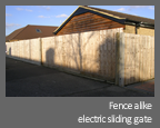
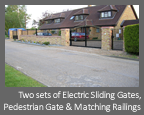
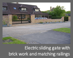
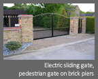
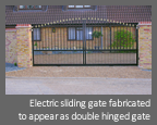
In addition to the standard methods used for constructing and commissioning of an electric sliding gate, below are few important facts to be taken into consideration.
Starting with the ground work, the use of purpose made galvanised ground gate track is preferable rather than ordinary wrought iron one. The galvanised gate track will minimise any corrosion stains on the final decorative driveway surface. (Granite work, resin bound gravel etc).
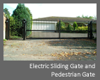
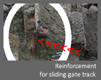
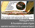
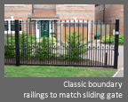
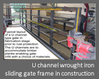
However the use of, off the shelf galvanised gate track directly on to the ground may not provide sufficient anchoring or even worse movement can occur over soft ground. To eliminate this issue the galvanised track can be welded on to a universal beam prior to installation. In some occasions the motor foundation plate can also be pre-welded on to the universal beam, providing additional strength to the operator. Photos 1 and 2 illustrate this method.
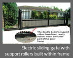
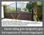
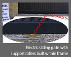
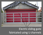
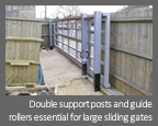
The support rollers are purpose made, sliding gate wheels allowing the side to side operation over the purpose made track. The use of double bearing support wheels is preferable over single bearings as this will ensure a long life span, whilst at the same time minimising side to side movement occurring from support rollers. For good stability the support rollers can be nested within the gate frame. Photos 3 and 4 illustrate this method.
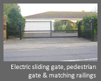
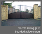
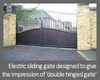
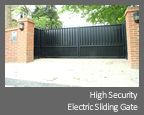
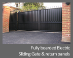
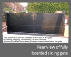
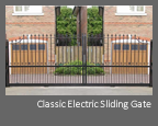
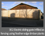
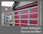
Electric sliding gates can be fabricated in various designs. An essential part of a sliding gate is the horizontally installed angle section. The angle section is to provide the horizontal level surface and therefore, enable the guide rollers to withhold the gate upright whilst allowing side to side operation. The position of the angle section over the gate height varies. It is however essential for the heavy part of the gate to be below the angle section. Photo 5 illustrates a bow top sliding gate. In this case the angle section has been installed on the third of the gate height. To achieve good stability the lowest part of the gate has been designed and fabricated heavier than the top part.
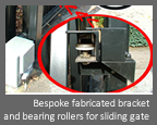
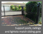
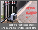
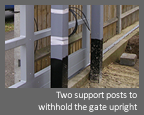
Sliding gates are usually equipped with support posts or safety posts, unless support can be achieved by other means. E.g walls etc. The support post is to provide a base where the brackets, equipped with guiding gate wheels is to be installed. Arts of Steel policy is to fabricate bespoke brackets for sliding gates. The bespoke fabricated brackets will neatly nest the guide rollers minimising risk of traps etc. The bespoke fabricated brackets will also be equipped with an overlapping guard ensuring that the gate cannot be lifted & provide additional safety. Our policy is also to use upgraded nylon dressed rollers equipped with enclosed self lubricated bearings rather than the standard Teflon type. The upgraded rollers in combination with the bespoke fabricated brackets, withhold the gate firmly upright, eliminating unwanted movement. Finally the support post in most occasions will be fabricated on the full height to act as a safety post in case of thr gate de-tracking due to vehicle collision. This type of brackets are clearly illustrated on photographs 6 and 7.
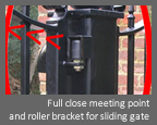
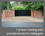
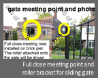
Sliding gates are usually most vulnerable on side to side movement, and easily de-tracked at the full closing position. This is due to the fact that the support rollers and specially fabricated brackets remain steady on the full opening position, whilst the gate extends itself to watch the full closing position. Therefore the full closing position is also where most of the gate is mainly unsupported. To eliminate any side to side movement and ensure that the gate will remain level at full close position the fabrication and installation of meeting points is essential. The meeting points consist of one nest usually installed onto the full close position and one guide roller installed onto the gate via bracket. The roller attached onto the gate will be driven into the fabricated nest on full closing position. These devices will also eliminate the risk of lifting and de-tracking for vandalism and therefore, provide extra security. The installation of these devices are clearly illustrated on photograph 8 and 9.
Safety Regulations in Europe
Sliding gates are often large, heavy and therefore more hazardous than swing gates. They can however, be equipped with appropriate safety devices making them some of the safest gate systems available.
All installations must meet with the Machinery directive 2006/42/EC with EN13241-1 being the regulations concerning gates. The installer of the gate is responsible for the conformity to regulations, not the manufacturer. The two main EN regulations that then apply are EN 12453 which describes the safety levels that should be observed when installing a gate, and EN12445 which describes the testing method that must be undertaken. The major points are the maximum amount of force at certain test points. Example - a maximum of 400N of force can be applied in the last 50, 300 and 500 mm of travel of a gate, after the initial impact the force must drop to 150N within 0.75 of a second and reduce to 25N within 5 seconds. During the mid travel of a gate the allowable force is 1400N.
A full risk assessment of the gates must take place with all crush, cutting points shown to the client with appropriate protection devices offered, a recommended maintenance program should also be provided. Finally the installer must confirm that all electrical equipment fitted has the European CE mark.
To conform to these regulations the gate system must be checked with a calibrated force tester and the full results kept in a technical file for 7 years. If the gate is not tested it does not comply. Most gate kits can be fitted with safety equipment so that these limits are achieved and so cover that part of EN13241-1.

